Blog - Open Vehicles Monitoring system repair - 2022
30-Jun-2022

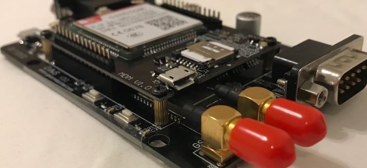
Defect/complaint: Open Vehicles module was brought in for repair because the modem part would not start when the box was connected to the CAN bus. It did boot via USB. The modem is responsible for the 3G/4G connection (using a SIM card).
Updated on: 30-06-2022
Investigation
The Open Vehicles module consists of two parts. The processor part (with ESP) and the modem. These printed circuit boards are connected to each other via two pin headers. They share a number of voltages including the 12Vdc (EXT_PWR), the 5Vdc (USB_5V) and the external voltage (made from the 5Vdc USB and 12Vdc voltage).
At both the 5Vdc from the USB and the 12Vdc, all voltages are present to start the modem. However, when the unit is connected to USB, the software indicates that the modem is ready. The software tries to start the modem via the 12Vdc connection on the CAN bus, but shuts itself down again.
According to the datasheet of the modem (SIM5360), the unit can be powered in two ways. Via 5Vdc (USB-Vbus) or via VBAT (4.2Vdc from a converter on the back of the modem PCB). In both cases, all voltages are present. Measured with a multimeter while starting, the voltage drops from 4.2 to 4.1Vdc. According to the datasheet, this module requires a minimum of 3.3Vdc to continue to function. 4.1Vdc seems well within the range.
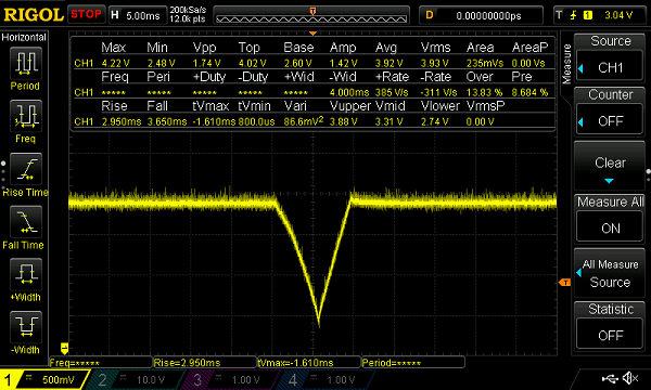
To further test whether there may be noise on the VBAT voltage line, the oscilloscope is connected. However, when starting the modem, it shows a different picture:

During startup, the voltage drops to 2.48Vdc very briefly. This is below the 3.3Vdc at which the modem can continue to operate. This happens faster than the multimeter can measure. The converter used in this circuit is an “AOZ1280CI”. It can supply about 2A. That should be more than enough to start this modem.
A load test shows that the voltage starts to drop from 50mA. Somewhere in the circuit, something goes wrong. Capacitors are in the margin along with the resistors.
Repair
The repair of the OVMS module consists of replacing the converter chip “AOZ1280CI”. Concerning the chip with six legs in the middle:
After the new chip has been placed, the VBAT voltage line supplies 2.5A and the modem starts up via the 12Vdc voltage from the CAN bus. Unit has been placed back in the car and is working properly again. Great project with great designed hardware!
If you have any questions about this topic, please leave a message.
If this was interesting, please consider making a voluntary donation. Which can here